Draw the equipotential surfaces corresponding to the uniform electric field in the Z direction.
Aditya Raj Anand Re-opened the question March 7, 2025
Equipotential Surfaces for a Uniform Electric Field in the Z-Direction
Concept
Equipotential surfaces are surfaces where the electric potential remains constant. In a uniform electric field, equipotential surfaces are always perpendicular to the field lines.
Given Condition
- The electric field is uniform and directed along the Z-axis.
- In a uniform field, the potential difference between two points is given by: V=−Ez⋅zV = – E_z \cdot z which means the potential only changes along the Z-direction.
Equipotential Surface Characteristics
- The equipotential surfaces must be planes parallel to the X-Y plane (i.e., perpendicular to the Z-axis).
- Each plane represents a constant potential VV, and different planes correspond to different potential values.
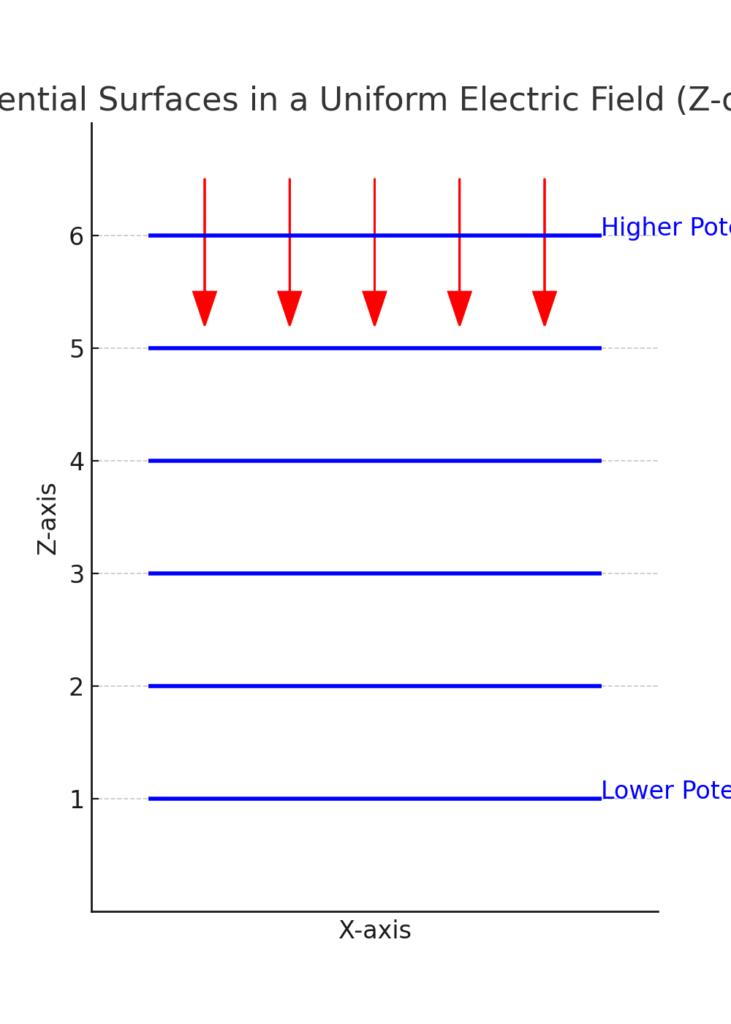
Diagram Explanation
- The Z-axis represents the direction of the electric field.
- The X-Y planes at different heights (Z = constant) represent different equipotential surfaces.
- Since the electric field is uniform, these surfaces are equally spaced.
Drawing
To visualize, draw:
- A set of horizontal planes (parallel to the X-Y plane) at different Z values.
- Label each plane with a different potential V1,V2,V3V_1, V_2, V_3, etc., decreasing or increasing along the Z-direction.
- Indicate the uniform electric field (E) as vertical arrows along the Z-axis.

Aditya Raj Anand Changed status to publish March 7, 2025
In a uniform electric field directed along the Z-axis, the equipotential surfaces are parallel planes perpendicular to the Z-axis.
Explanation:
- Uniform Electric Field: The field lines are straight and parallel along the Z-axis.
- Equipotential Surfaces: These surfaces are always perpendicular to the direction of the electric field.
- Resulting Shape: Since the field is uniform in the Z direction, the equipotential surfaces must be horizontal planes (parallel to the XY-plane).
- Spacing of Surfaces: The potential difference between two equipotential surfaces is constant, so they are equally spaced along the Z-axis.
Diagram Representation:
The equipotential surfaces can be drawn as a series of horizontal planes (XY-planes) stacked at different Z-values, like this:
(z = V1)  ------------------  (higher potential)
(z = V2)  ------------------
(z = V3)  ------------------  (lower potential)
Aditya Raj Anand Changed status to publish March 7, 2025
Write your answer.